|
|
Overview
Preparation
Cores
Shear Web & Bottom Skin
Top Skin
Epilog
 |
Building the RONCZ Canard
I built a canard last year which had a few undesirable characteristics. I did not like the consistency of the profile or the weight. At around 30 pounds, it was close to 50% overweight.
This prompted a lot of concern and I finally decided that the only right thing to do would be to remanufacture the part using better technique, higher quality materials and do it all in 10 days.
|
 |
Jig Construction
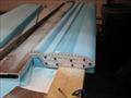
My jig is a bit different when compared to the plans approach.
|
 |
The individual jig blocks were cut per plans from 3/4 inch plywood. Once that was completed, I cut a 1" x 2" notch in two places on each block. I placed my jig blocks per plans and inserted a piece of 1x2 extruded aluminum into the matching slots to create two rails that run the full length of the table and held them in place with some bondo. This will assure a consistent straight part throughout the construction process.
|
 |
The same approach was used for the top skin jig construction.
The jig was not bonded to the table as is outlined in the plans but is instead, left free to enable the entire jig, core and layups to be inserted into the vacuum bag as a single unit. The ends can be clamped to the table to provide a secure foundation during the cure.
At the same time, I created a "heat tent" out of 2 inch foam. In tests that I conducted, a layup that is covered with an electric blanket and then enclosed within the foam shell will reach a curing temperature of +100 degrees Fahrenheit. This will ensure that the epoxy maintains a low viscosity during the cure which will promote both a good wet-out as well as facilitating the transfer of the residual epoxy into the bleeder/breather layer.
|
 |
Cores (Full Length Spar)
I used a different approach when cutting my cores. Instead of cutting them as four pieces (two with spar cap trough and two end pieces) I ran the spar cap trough all the way to the ends which resulted in two pieces 65 inches in length. This was suggested by J.D. from Infinity Aerospace as a means to simplify the construction of the canard while adding both strength and ensuring a straight part upon completion.
|
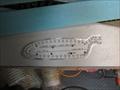 |
Oversized Hotwire
The cores were cut oversized by .25 inches and then sanded to the templated profile. I found that working a hotwire this long made it almost impossible to get the results I needed due to wire lag. It just seemed logical to go with an oversized core and sand to the proper profile. The exception to this is the cutouts for the spar trough. Those were cut to the finished dimensions the first time through.
|
 |
Sanded to size
As you can see, each canard half is 65 inches in length. I used a piece of 1x4 aluminum extrusion, six feet in length for my sanding block. This was fitted with 36 grit sandpaper on one side and 60 grit on the other. It is a little time consuming but the bottom line is you end up with a perfect profile.
An alternative would be to buy precut cores from someone such as Eureka CNC. I have not discussed the full length spar cap troughs with them but I would have to believe that they could make such an adjustment to their process.
|
 |
Step 1: Shear Web Prep
Once my profile was done, I drilled my dowel alignment holes as spelled out in the plans and then cut the nose off via the hot wire. At this point I assembled my two halves using 3M #78 spray adhesive. I fitted two pieces of 1x2 aluminum extrusion on either side (top & bottom) and clamped them in place until the glue had set.
|
 |
Shear Web Layup (1/25/2009)
With the two halves bonded the pieces together I buried my nut plate for the canard attachments (which I purchased from the Cozygirrrls .) I used two strips of scrap Formica to identify the location of the bolt holes in the nutplates. These would be used in a later step when the holes are opened up in preparation to install the tabs that will eventually connect the canard to the fuselage. The bolt holes were then filled with a clear silicone caulk to avoid fouling the threaded portion with epoxy. Prior to filling the holes, the area was masked off to minimize any possible contamination of the bonding surfaces.
The next step was to lay up my shear web. I jigged my canard so it would stand on it’s tail and proceeded to add my layers of glass. Upon completion I installed my peel ply, perf ply and breather/bleeder layer and slipped it into the vacuum bag. Again, final alignment was accomplished by clamping the two 1x2 lengths of extrusion to either side of the spar cap and then flipping it trailing edge up.
|
 |
Step 2: Tabs (1/26/2009)
The multiple plies are added over the top of the nutplate location. Once these have cured I reattached the location guide and drilled out the location of the bolt holes. I bolted the tabs in place and then added a small bid layup on the inside edge of the tabs where they will come in contact with the spar cap. This is an extra step that will be required for me to provide a barrier between the aluminum tabs and the carbon fiber of the spar cap. If you are using the standard glass roving tapes, this will not be required.
I decided to use the West Systems 703 Carbon Fiber tapes for three reasons.
- The tapes are stronger.
- They have a predictable and measurable property which will allow me to calculate the tape lengths as well as the number needed.
- Weight: The strength to weight ratio is much higher with these tapes.
I prefer this to the plans method which is to fill the trough. I believe this is an area that cost me extra weight in my previous attempt. If I was going to build this with glass tapes, I think I would lean toward the West 713 tapes due to the predictable nature of the tapes.
|
 |
Step 3: Bottom Spar Cap (1/26/2009)
I created a spreadsheet which I used to calculate the number and length of the tapes that would be required. The Idea is to measure the depth o the spar cap trough at the outboard location and then divide that by the thickness of the tapes. That will give you all of the full length tapes which can be cut ahead of time.
Next I measured the depth on the inboard portion of the trough. I subtracted the outboard measurement form that and divided that number by the thickness of the tapes. That will give me the number of additional tapes required. One I divide the length of the canard by that number, I end up with the increment by which I need to shorten each successive tape.
All the tapes were precut and dry fit prior to pumping any epoxy. The ends were angled to allow for a more gradual transition between the layers.
The next step was to layup all the tapes and let me tell you, all of those statements about Carbon Fiber being difficult to work with went right out the window. This stuff wetted out just fine and I was able to squeegee any excess epoxy off the ends and into a mixing cup for reuse on the next tape.
I would estimate that the total time was cut in half and that is with me working solo. On the previous attempt, my son mixed epoxy for me and it still took much longer due to all of the extra effort required when using the standard tapes. Combine that with the fact that you can't precut with any accuracy and you have one long layup session.
Once everything was wetted out and squeegeed to my satisfaction, I added my peel ply, perf ply and bleeder/breather layer and popped it into the vacuum bag, jig and all. The vacuum held the canard tight to the extruded aluminum rails throughout the cure to insure a very straight canard.
Once the vacuum was running, I laid on the electric blankets (2) folded to width and enclosed the entire layup in the foam heat box.
|
 |
Step 4: Hardpoints (1/27/2009)
I really do not like the plans method of installing hard point so I developed a different approach and install them prior to applying the bottom skin.
I cut out all of the hard point locations using a handheld hotwire tool used for sculpting foam. I believe sign makers use them. It uses a very fine wire and works great.
I used the waste piece as a template and traced the pattern onto the last-a-foam. I cut all of the hard points out removing the tail piece as I went. This gives me the final profile I'm looking for. I added back the tail using the wing foam from the waste pieces and microed it all into position. Once this cures, I'll clean up any high spots using the
Fein Multi-master.
|
 |
Step 5: Bottom Skin (1/29/2009)
have the hard points cleaned up and microed the foam in preparation for the bottom skin. I also sanded all of the transition points (steps) of the different tape lengths and added some flox to smooth out any areas that would have resulted in an abrupt transition.
The skin layers were applied without incident and I again added the peel ply, perf-ply and bleeder/breather material prior to vacuum bagging the entire assembly. The electric blankets are put in place and the foam boxed is placed over the entire assembly for an overnight cure.
|
 |
Step 6: Nav Antenna (1/30/2009)
I checked the profile of the bottom rear curve that terminates with the trailing edge. In some areas the edge seemed to droop a bit. I heated these areas up with a heat gun and then used a pair of sheet metal pliers (the type with a 3 inch wide jaw to shape sheet metal with) and then allowed it to cool down while I held it in place. This had to be addressed prior to attaching the canard to the jig with Bondo.
Because the canard also functions as a flap, it is imperative that the shape be exactly as the plans dictate. This is not an area to be taken lightly. I don't know what the implications are of a deformation in this area .... nor do I wish to find out.
I swapped some emails with James Redmon (Berkut 13) with regards to the Nav antenna. I was concerned that the Carbon Fiber may pose a problem for me. I was instructed to add a ply of BID fiberglass to insulate the antenna from the Carbon Fiber and proceed as you normally would.
I put this antenna on top. I know a lot of builders put this on the bottom side but it appears to me that a straight shot through the bottom of the canard and then solder the foil on top, would be a simpler aproach. It seems to work fine so we're off and running again.
If I have any problems with this arrangement, I'll attach a high gain antenna (ACS part number 11-04261) to the underside of the canard staying close to the nose of the canard in order to avoid the likelihood of interference.
I really do not anticipate any problems with this.
|
 |
Step 7: Top Skin (1/31/2009)
Well here we are .... the final layup.
This was pretty uneventful. The top skin layups were installed tonight. The only issues I experienced were centered around the way the glass wraps around the nose.
I propped the jig up so that the nose was inclined at about a 45 degree angle just to make the process of wrapping the plies around that area a little easier and improve the visibility of the underside.
Again the same procedures were followed to prep it for the vacuum bag and let it cure overnight.
|
 |
Conclusion (2/1/2009)
The rebuild of the canard is complete and I was able to stay within the 10 day schedule I proposed. The end result was a weight savings of 10lb 15oz. The total weight of the canard without the tips and elevator, is 19lb, 1oz.
When you consider that this is better than one percent of the total empty weight, that is a significant savings. I'm just glad that I took this step at this point of the build. Now I can apply the same level of vigulance to the other areas of the project which will only serve to improve performance.
|
|